design_guess#
- esis.flights.f2.optics.design_guess(grid=None, axis_channel='channel', num_distribution=11)[source]#
Load the starting point (or guess) for optimization of the ESIS-II design.
This model uses the entire optical bench length for increased resolution.
- The changes from ESIS-I are as follows:
The target wavelengths have changed to Ne VII 46.5 nm and Si XII 49.9 nm.
The primary mirror is moved back by 6 holes on the optical bench.
The gratings are moved forward by 2 holes on the optical bench.
The filter position and orientation has been adjusted to account for the shallower beam.
To account for these changes, the angle, radius of curvature, and the ruling parameters of the grating need to be adjusted. This function uses the grating equation and Poletto and Thomas [2004] to estimate these parameters. These estimates are intended to be used as a starting point for a local minimization procedure to find the best-fit values of these parameters.
- Parameters:
grid (None | ObjectVectorArray) – sampling of wavelength, field, and pupil positions that will be used to characterize the optical system.
axis_channel (str) – The name of the logical axis corresponding to changing camera channel.
num_distribution (int) – number of Monte Carlo samples to draw when computing uncertainties
- Return type:
Notes
Let \(\mathbf{a}\) be the vector pointing from the apex of the grating to the center of the field stop, and let \(\mathbf{b}_i\) be the vector pointing from the apex of the grating to target location of wavelength \(i\) on the sensor.
The angle between \(\mathbf{a}\) and the optic axis, \(\hat{\mathbf{z}}\), is then
\[a = \arctan \left( \frac{\mathbf{a} \cdot \hat{\mathbf{x}}} {\mathbf{a} \cdot \hat{\mathbf{z}}} \right),\]and similarly for \(\mathbf{b}_i\),
\[b_i = \arctan \left( \frac{\mathbf{b}_i \cdot \hat{\mathbf{x}}} {\mathbf{b}_i \cdot \hat{\mathbf{z}}} \right).\]If the grating is rotated about the \(\hat{\mathbf{y}}\) axis by \(\theta\), then the relationship between the incident/diffracted angles and \(a\)/\(b\) is
\[\begin{split}\alpha &= a - \theta \\ \beta_i &= b_i - \theta,\end{split}\]and the grating equation becomes
(1)#\[\sin{(a - \theta)} + \sin{(b_i - \theta)} = \frac{m \lambda_i}{d},\]where \(m\) is the diffraction order, \(\lambda_i\) is the wavelength, and \(d\) the grating ruling spacing.
If we consider two target wavelengths, \(\lambda_1\) and \(\lambda_2\), Equation (1) is a system of two equations which can be solved to find the grating yaw angle,
\[\theta = -\arccos \left[ \frac{(\lambda_2 - \lambda_1) \cos a + \lambda_2 \cos b_1 - \lambda_1 \cos b_2} {\sqrt{2} \sqrt{ \lambda_1^2 - \lambda_1 \lambda_2 + \lambda_2^2 + \left( \lambda_1 - \lambda_2)(\lambda_1 \cos (a-b_2) - \lambda_2 \cos(a-b1) \right) - \lambda_1 \lambda_2 \cos(b1-b2) } } \right],\]and the ruling spacing,
\[d = \frac{m \lambda_1}{\sin(a - \theta) + \sin(b_1 - \theta)}.\]The radius of the grating surface can be found using Equation 31 of Poletto and Thomas [2004],
\[R = r_a (\cos \alpha + \cos \beta) \frac{M_c}{1 + M_c},\]where \(r_a = |\mathbf{a}|\) is the length of the entrance arm, \(\beta_c\) is the diffracted angle of the center wavelength, \(\lambda_c = (\lambda_1 + \lambda_2) / 2\), \(M_c = r_b / r_a\) is the magnification of the center wavelength, and \(r_b = |\mathbf{b}_c|\) is the length of the exit arm at the center wavelength.
Finally, the linear term for the ruling density VLS law can be found using Equation 26 of Poletto and Thomas [2004],
\[\sigma_1 = -\frac{1}{m \lambda_c} \left( \frac{\cos^2 \alpha}{r_a} + \frac{\cos^2 \beta}{r_b} - \frac{\cos \alpha + \cos \beta}{R} \right).\]These equations taken together can be used to formulate a close guess to an optimal ESIS-II design.
Examples
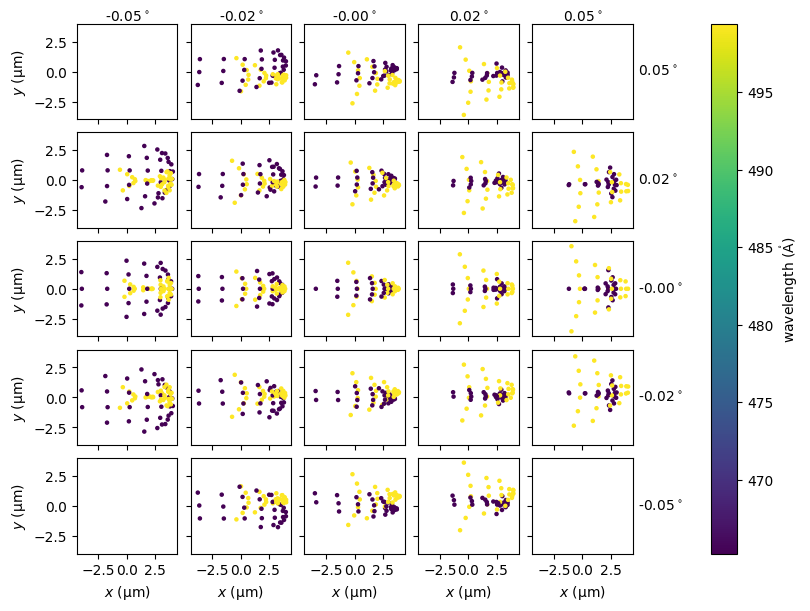
Plot a spot diagram for this design.
# Import this package
import esis

# Load this design into memory
instrument = esis.flights.f2.optics.design_guess(num_distribution=0)

# Lower the number of field angles for clearer plotting
instrument.field.num = 5

# Plot the spot diagram for each field angle
fig, ax = instrument.system.spot_diagram()
Print the calculated parameters of this design.
instrument.grating.sag.radius.ndarray
\[-923.98516 \; \mathrm{mm}\]instrument.grating.yaw.ndarray
\[-2.4279253\mathrm{{}^{\circ}}\]instrument.grating.rulings.spacing.coefficients[0].ndarray
\[5578.9932 \; \mathrm{\mathring{A}}\]instrument.grating.rulings.spacing.coefficients[1].ndarray
\[-1.8287944 \times 10^{-5} \; \mathrm{\frac{\mu m}{mm}}\]References to
esis.flights.f2.optics.design_guess